|
Home2L - C/C++ API v1.4-2-g83f4c (2025-08-23)
Smart Tools for a Private Home
|
Loading...
Searching...
No Matches
|
Home2L - C/C++ API v1.4-2-g83f4c (2025-08-23)
Smart Tools for a Private Home
|
#include <stdint.h>#include <stdbool.h>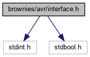
Go to the source code of this file.
Classes | |
| struct | SBrRequest |
| Request message. More... | |
| struct | SBrReply |
| Reply message. More... | |
| struct | SBrFeatureRecord |
| Brownie feature record (stored in VROM). More... | |
| struct | SBrConfigRecord |
| Brownie configuration record (stored in EEPROM). More... | |
Macros | |
| #define | BR_MEM_BLOCKSIZE (1 << BR_MEM_BLOCKSIZE_SHIFT) |
| Block size for 'memRead'/memWrite' operations. Note: This value is an integral part of the communication protocol and must not be changed. | |
| #define | BR_REQUEST_SIZE_MAX ((int) sizeof (TBrRequest)) |
| Maximum length of a request. | |
| #define | BR_REQUEST_SIZE_MIN 2 |
| Mminimum length of a valid request. | |
| #define | BR_REPLY_SIZE_MAX ((int) sizeof (TBrReply)) |
| Maximum length of a request. | |
| #define | BR_REPLY_SIZE_MIN 1 |
| Minimum length of a valid reply. | |
| #define | BR_REPLY_SIZE_STATUS 1 |
| Length of a status-only reply. | |
| #define | BR_OP_REG_READ(REG) ((0x00 | (REG))) |
| Build "register read" opcode. | |
| #define | BR_OP_REG_WRITE(REG) ((0x40 | (REG))) |
| Build "register write" opcode. | |
| #define | BR_OP_MEM_READ(BLKADR) (0x80 | ((BLKADR) >> 8)) |
| Build "memory read" opcode. | |
| #define | BR_OP_MEM_WRITE(BLKADR) (0x90 | ((BLKADR) >> 8)) |
| Build "memory write" opcode. | |
Time Constants and Conversion ... | |
The CPU frequency BR_CPU_FREQ must match the AVR compiler/linker setting of F_CPU. The Brownie firmware uses a hardware timer (no regular timer interrupt) to measure time. The time unit is referred to as a Brownie Tick. The duration of a Brownie Tick is / should be in the order of one millisecond, but the exact duration somewhat depends on the hardware. | |
| #define | BR_CPU_FREQ 1000000 |
| CPU clock frequency. | |
Memory Layout | |
| #define | BR_MEM_PAGE_FLASH 0x0 |
| ... 0x7: Program flash memory pages (one page = 0x100 * BR_MEM_BLOCKSIZE bytes) | |
| #define | BR_MEM_PAGE_SRAM 0x8 |
| SRAM base page. | |
| #define | BR_MEM_PAGE_EEPROM 0x9 |
| EEPROM base page. | |
| #define | BR_MEM_PAGE_VROM 0xa |
| Version ROM base page (mapped to data array in program) | |
| #define | BR_FLASH_PAGESIZE 0x40 |
| Size of a flash page to be used by communication peers (e.g. TWI masters). | |
| #define | BR_FLASH_BASE_MAINTENANCE 0x0040 |
| Byte address defining the start of the maintenance system. | |
| #define | BR_FLASH_BASE_OPERATIONAL 0x0a00 |
| Byte address defining the border between the maintenance and application system. Addresses below this are reserved for the maintenance system. | |
| #define | BR_VROM_SIZE sizeof (TBrFeatureRecord) |
| Size of the VROM. | |
| #define | BR_EEPROM_ID_BASE 0x0000 |
| Location of the ID string in the EEPROM. | |
| #define | BR_EEPROM_ID_SIZE sizeof (TBrIdRecord) |
| Size of the ID record. | |
| #define | BR_EEPROM_CFG_BASE 0x0000 + BR_EEPROM_ID_SIZE |
| Location of the configuration record in the EEPROM. | |
| #define | BR_EEPROM_CFG_SIZE sizeof (TBrConfigRecord) |
| Size of the configuration record. | |
... Feature Bits ... | |
| #define | BR_FEATURE_MAINTENANCE 0x0001 |
| Is maintenance system (usually, everything else is ommitted/zero then) | |
| #define | BR_FEATURE_NOTIFY 0x0004 |
| Does host notification (usually 0 for primary hubs and maintenance systems, else 1) | |
| #define | BR_FEATURE_TWIHUB 0x0008 |
| Is TWI hub. | |
| #define | BR_FEATURE_ADC_0 0x0010 |
| Has ADC #0. | |
| #define | BR_FEATURE_ADC_1 0x0020 |
| Has ADC #1. | |
| #define | BR_FEATURE_ADC_PASSIVE 0x0400 |
| ADCs run in passive mode (sampling on demand, no change reporting) | |
| #define | BR_FEATURE_UART 0x0040 |
| Has UART (e.g. for RS485) | |
| #define | BR_FEATURE_TEMP 0x0080 |
| Has temperature sensor (TSic 206/306 over ZACwire) | |
| #define | BR_FEATURE_SHADES_0 0x0100 |
| Has shades actuator #0. | |
| #define | BR_FEATURE_SHADES_1 0x0200 |
| Has shades actuator #1. | |
... Matrix Dimensions ... | |
(for SBrFeatureRecord::matDim) | |
... MCU Type IDs ... | |
(for SBrFeatureRecord::mcuType and for the 'config.h') | |
| #define | BR_MCU_NONE 0 |
| No or unknown MCU type. | |
| #define | BR_MCU_ATTINY85 1 |
| AVR ATtiny85 (8 pins) or any software- and pin-compatible model. | |
| #define | BR_MCU_ATTINY84 2 |
| AVR ATtiny84 (14 pins) or any software- and pin-compatible model. | |
| #define | BR_MCU_ATTINY861 3 |
| AVR ATtiny861 (20 pins) or any software- and pin-compatible model. | |
General ... | |
| #define | BR_REGISTERS 0x40 |
| Number of registers. | |
Notification register(s) ... | |
| #define | BR_REG_CHANGED 0x00 |
| Change indicator register; Reading resets all bits. | |
| #define | BR_CHANGED_CHILD 0x01 |
| – [BR_REG_CHANGED] (hubs only) any child has reported a change | |
| #define | BR_CHANGED_GPIO 0x02 |
| – [BR_REG_CHANGED] any GPIO input changed | |
| #define | BR_CHANGED_MATRIX 0x04 |
| – [BR_REG_CHANGED] any sensor matrix switch changed | |
| #define | BR_CHANGED_ADC 0x40 |
| – [BR_REG_CHANGED] a new ADC sample value exists (only if ADC_PERIOD > 0) | |
| #define | BR_CHANGED_UART 0x08 |
| – [BR_REG_CHANGED] UART status register has changed | |
| #define | BR_CHANGED_SHADES 0x10 |
| – [BR_REG_CHANGED] state of any shades changed (actuator or button, not position) | |
| #define | BR_CHANGED_TEMP 0x20 |
| – [BR_REG_CHANGED] temperature changed (only if configured) (DEPRECATED: may be removed in the future) | |
Registers for GPIO, Timer, Temperature ... | |
| #define | BR_REG_GPIO_0 0x02 |
| GPIOs (0..7): One bit per GPIO. | |
| #define | BR_REG_GPIO_1 0x03 |
| GPIOs (8..15, if present): One bit per GPIO. | |
| #define | BR_REG_TICKS_LO 0x04 |
| Ticks timer (low byte) | |
| #define | BR_REG_TICKS_HI 0x05 |
| Ticks timer (high byte); low byte must be read first, reading low latches high. | |
| #define | BR_REG_TEMP_HI 0x07 |
| Temperature (little endian; reading low latches high). | |
ADC registers ... | |
(NOT IMPLEMENTED YET) | |
| #define | BR_REG_ADC_0_LO 0x08 |
| ADC #0 low (bit 7 = ADC.1, bit 6 = ADC.0) | |
| #define | BR_REG_ADC_0_HI 0x09 |
| ADC #0 high (ADC.9 .. ADC.2); reading low latches high. | |
| #define | BR_REG_ADC_1_LO 0x0a |
| ADC #1 low (bit 7 = ADC.1, bit 6 = ADC.0) | |
| #define | BR_REG_ADC_1_HI 0x0b |
| ADC #1 high (ADC.9 .. ADC.2); reading low latches high. | |
UART registers ... | |
Notes on the UART operation: The RX buffer status value (0..7) indicates how many bytes can be received without error:
The TX buffer status value (0..7) indicates how many bytes can be transferred without error:
| |
| #define | BR_REG_UART_CTRL 0x0c |
| UART control register. | |
| #define | BR_REG_UART_STATUS 0x0d |
| UART status register. | |
| #define | BR_REG_UART_RX 0x0e |
| UART receive register (must be accessed with the "no resend" option) | |
| #define | BR_REG_UART_TX 0x0f |
| UART transfer register (must be accessed with the "no resend" option) | |
| #define | BR_UART_CTRL_RESET_RX 0x01 |
| – [BR_REG_UART_CTRL] Reset RX buffer | |
| #define | BR_UART_CTRL_RESET_TX 0x02 |
| – [BR_REG_UART_CTRL] Reset TX buffer | |
| #define | BR_UART_CTRL_RESET_FLAGS 0x04 |
| – [BR_REG_UART_CTRL] Reset status flags (overflow, error) | |
| #define | BR_UART_STATUS_RX_MASK 0x07 |
| – [BR_REG_UART_STATUS] Mask for RX buffer status values (3 bits, values 0..7) | |
| #define | BR_UART_STATUS_RX_SHIFT 0 |
| – [BR_REG_UART_STATUS] RX buffer status shift | |
| #define | BR_UART_STATUS_TX_MASK 0x38 |
| – [BR_REG_UART_STATUS] Mask for TX buffer status values (3 bits, values 0..7) | |
| #define | BR_UART_STATUS_TX_SHIFT 3 |
| – [BR_REG_UART_STATUS] TX buffer status shift | |
| #define | BR_UART_STATUS_OVERFLOW 0x40 |
| – [BR_REG_UART_STATUS] An RX buffer overflow occured, at least one byte was lost | |
| #define | BR_UART_STATUS_ERROR 0x80 |
| – [BR_REG_UART_STATUS] A receive error (parity or frame) occured; Note: not implemented yet | |
Matrix registers ... | |
Notes on matrix events: Reading removes the oldest entry from the (internal) event queue, the overflow state is not left on read. Writing 0x80 clears the queue and overflow state. The event register allows to detect the precise order of events, which may be used to detect if a window is tilted or closed. This register is not synchronized with any of the raw matrix registers. Initialization/Recovery after overflow or read errors can be done as follows:
The cycle counter is incremented whenever the internal row counter wraps around. It helps to identify whether events have truly happend in the order the events are delivered by the queue. Two events e1 and e2 received in this order with ecycle values of c1/c2 and rows of r1/r2, respectively, are proven to have happened in this order, if (c2 * #rows + r2) - (c1 * #rows + r1) >= #rows If this condition is not met, the real order may be different due to sampling inaccuracies. If this is unwanted, the sampling frequency should be increased (MATRIX_T_PERIOD). | |
| #define | BR_REG_MATRIX_7 0x17 |
| Sensor matrix: raw data (one byte per row, up to 8x8 = 64 bits) | |
| #define | BR_REG_MATRIX_EVENT 0x18 |
| Sensor matrix: Next matrix event. | |
| #define | BR_REG_MATRIX_ECYCLE 0x19 |
| Cycle counter of last read matrix event. | |
| #define | BR_MATRIX_EV_VAL_SHIFT 6 |
| – [BR_REG_MATRIX_EVENT] Bit 6 = value | |
| #define | BR_MATRIX_EV_ROW_SHIFT 3 |
| – [BR_REG_MATRIX_EVENT] Bits 5..3 = row | |
| #define | BR_MATRIX_EV_COL_SHIFT 0 |
| – [BR_REG_MATRIX_EVENT] Bits 2..0 = col | |
| #define | BR_MATRIX_EV_EMPTY 0x80 |
| – [BR_REG_MATRIX_EVENT] Special value: event queue empty | |
| #define | BR_MATRIX_EV_OVERFLOW 0x81 |
| – [BR_REG_MATRIX_EVENT] Special value: overflow | |
Shades registers ... | |
Notes on shades control:
| |
| #define | BR_REG_SHADES_STATUS 0x20 |
| Shades status register. | |
| #define | BR_REG_SHADES_0_POS 0x22 |
| Shades #0: Current position (0..100); 0xff = "unknown". | |
| #define | BR_REG_SHADES_0_RINT 0x23 |
| Shades #0: Internal request (0..100 or 0xff = "none") | |
| #define | BR_REG_SHADES_0_REXT 0x24 |
| Shades #0: External request (0..100 or 0xff = "none") | |
| #define | BR_REG_SHADES_1_POS 0x25 |
| Shades #1: Current position (0..100); 0xff = "unknown". | |
| #define | BR_REG_SHADES_1_RINT 0x26 |
| Shades #1: Internal request (0..100 or 0xff = "none") | |
| #define | BR_REG_SHADES_1_REXT 0x27 |
| Shades #1: External request (0..100 or 0xff = "none") | |
| #define | BR_SHADES_0_ACT_UP 0x01 |
| – [BR_REG_SHADES_STATUS] Shades #0 actor is currently moving up | |
| #define | BR_SHADES_0_ACT_DN 0x02 |
| – [BR_REG_SHADES_STATUS] Shades #0 actor is currently moving down | |
| #define | BR_SHADES_0_BTN_UP 0x04 |
| – [BR_REG_SHADES_STATUS] Shades #0 up button is pushed (= button down after debouncing) | |
| #define | BR_SHADES_0_BTN_DN 0x08 |
| – [BR_REG_SHADES_STATUS] Shades #0 down button is pushed (= button down after debouncing) | |
| #define | BR_SHADES_1_ACT_UP 0x10 |
| – [BR_REG_SHADES_STATUS] Shades #1 actor is currently moving up | |
| #define | BR_SHADES_1_ACT_DN 0x20 |
| – [BR_REG_SHADES_STATUS] Shades #1 actor is currently moving down | |
| #define | BR_SHADES_1_BTN_UP 0x40 |
| – [BR_REG_SHADES_STATUS] Shades #1 up button is pushed (= button down after debouncing) | |
| #define | BR_SHADES_1_BTN_DN 0x80 |
| – [BR_REG_SHADES_STATUS] Shades #1 down button is pushed (= button down after debouncing) | |
Debugging ... | |
| #define | BR_REG_DEBUG_0 0x38 |
| Debug register 0 (for debugging purposes only) | |
| #define | BR_REG_DEBUG_1 0x39 |
| Debug register 1 (for debugging purposes only) | |
| #define | BR_REG_DEBUG_2 0x3a |
| Debug register 2 (for debugging purposes only) | |
| #define | BR_REG_DEBUG_3 0x3b |
| Debug register 3 (for debugging purposes only) | |
System control registers ... | |
| #define | BR_REG_FWBASE 0x3d |
| Firmware base and boot vector location. | |
| #define | BR_REG_CTRL 0x3e |
| Control register. | |
| #define | BR_REG_MAGIC 0x3f |
| Magic value (returns BR_MAGIC after reset) | |
| #define | BR_CTRL_UNLOCK_EEPROM 0x01 |
| – [BR_REG_CTRL] Setting this bit unlocks EEPROM for writing | |
| #define | BR_CTRL_UNLOCK_FLASH 0x02 |
| – [BR_REG_CTRL] Setting this bit unlocks flash memory and SRAM | |
| #define | BR_CTRL_HUB_RESURRECTION 0x04 |
| – [BR_REG_CTRL] Setting this bit puts TWI hub into resurrection mode | |
| #define | BR_CTRL_REBOOT 0xe0 |
| – [BR_REG_CTRL] Writing this value lets the device reboot | |
| #define | BR_CTRL_REBOOT_NEWFW 0xa0 |
| – [BR_REG_CTRL] Writing this value changes the interrupt table according to BR_REG_FWBASE and reboots the device | |
Typedefs | |
| typedef struct SBrRequest | TBrRequest |
| Request message. | |
| typedef struct SBrReply | TBrReply |
| Reply message. | |
Brownie ID (EEPROM, Run-Time Changable) ... | |
| typedef char | TBrIdRecord[32] |
| Brownie ID (stored in EEPROM). | |
Configuration Record (EEPROM, Run-Time Changeable) ... | |
| typedef struct SBrConfigRecord | TBrConfigRecord |
| Brownie configuration record (stored in EEPROM). | |
Enumerations | |
| enum | EBrStatus { brOk = 0 , brIncomplete , brUnchecked , brRequestCheckError , brReplyCheckError , brIllegalOperation , brForbidden , brNoBrownie , brNoDevice , brNoBus , brNoReply = 0x0f , brEND } |
Functions | |
| int8_t | BrRequestSize (uint8_t op) |
| Get the size of a request message in bytes, depending on the operation. | |
| void | BrRequestPackage (TBrRequest *msg) |
| Complete the message for sending (i.e. add checksum). | |
| EBrStatus | BrRequestCheck (TBrRequest *msg, int8_t bytes) |
| Check received message. 'bytes' is the number of valid bytes in the beginning of the message. | |
| int8_t | BrReplySize (uint8_t op) |
| Get the size of a reply message in bytes, depending on the operation. | |
| void | BrReplyPackage (TBrReply *reply, int8_t len) |
| Complete the reply for sending (i.e. add checksum). | |
| EBrStatus | BrReplyCheck (TBrReply *reply, uint8_t op, int8_t bytes) |
| Check received message. 'bytes' is the number of received bytes. | |
Version and Feature Record (VROM, Compile-Time) ... | |
| #define | BR_MAGIC 0xb1 |
| Magic byte value to identify this device as a brownie. | |
| #define | brFeatureRecordRcVec0 offsetof (TBrFeatureRecord, features) |
| Offset of first byte of the feature code stored in the database (key "features") and relevant for resources. | |
| #define | brFeatureRecordRcVec1 offsetof (TBrFeatureRecord, reserved) |
| Offset of first byte behind the feature code stored in the database (key "features") and relevant for resources. | |
| typedef struct SBrFeatureRecord | TBrFeatureRecord |
| Brownie feature record (stored in VROM). | |